Boolean
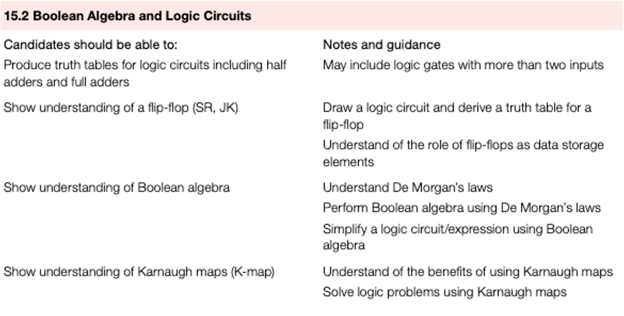
Boolean algebra
Boolean algebra is named after the mathematician George Boole.
It is a form of algebra linked to logic circuits and is based on the two statements:
TRUE (1)
FALSE (0)
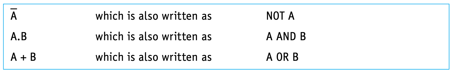
The notation used in this book to represent these two Boolean operators is:
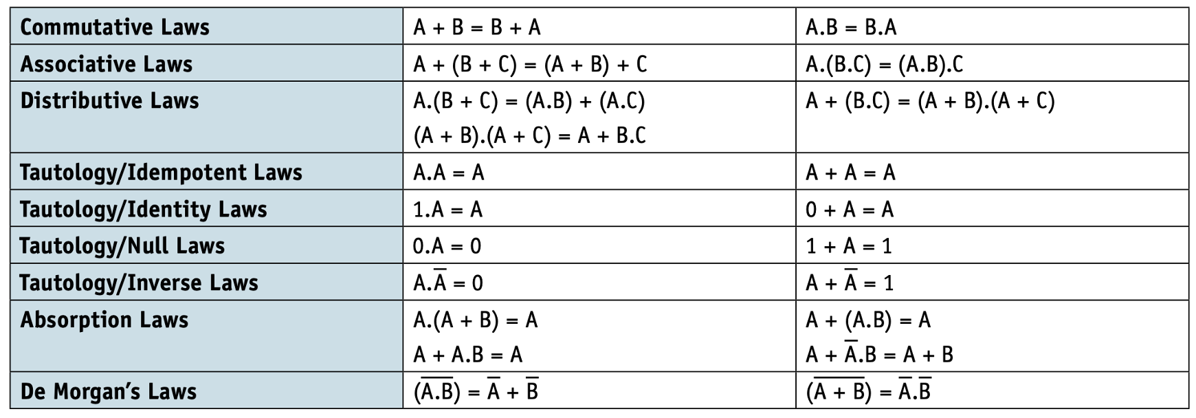
Rules
The rules that govern Boolean algebra. It also includes De Morgan’s Laws.
Simplification using Boolean algebra
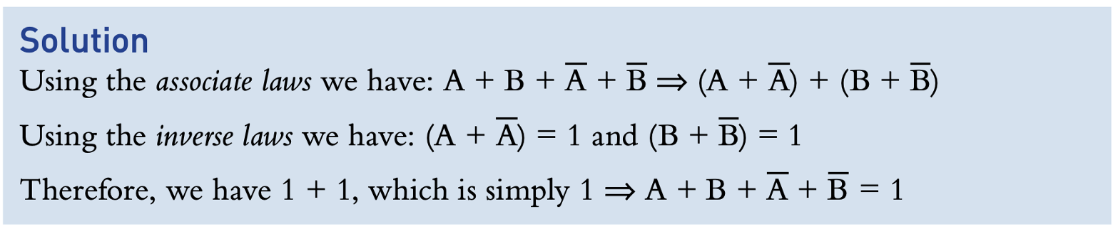
- Simplify
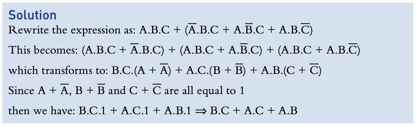
- Simplify
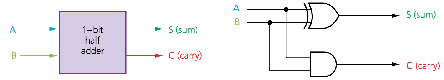
Half adder
One of the basic operations in any computer is binary addition.
The half adder circuit is the simplest circuit.
This carries binary addition on 2 bits generating two outputs
- the sum bit (S)
- the carry bit (C).
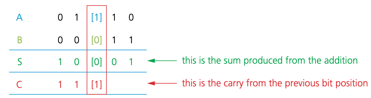
Consider 1 + 1. It will give the result 1 0 (denary value 2).
The ‘1’ is the carry and ‘0’ is the sum.
| A | B | S | C |
|---|---|---|---|
| 0 | 0 | 0 | 0 |
| 0 | 1 | 1 | 0 |
| 1 | 0 | 1 | 0 |
| 1 | 1 | 0 | 1 |
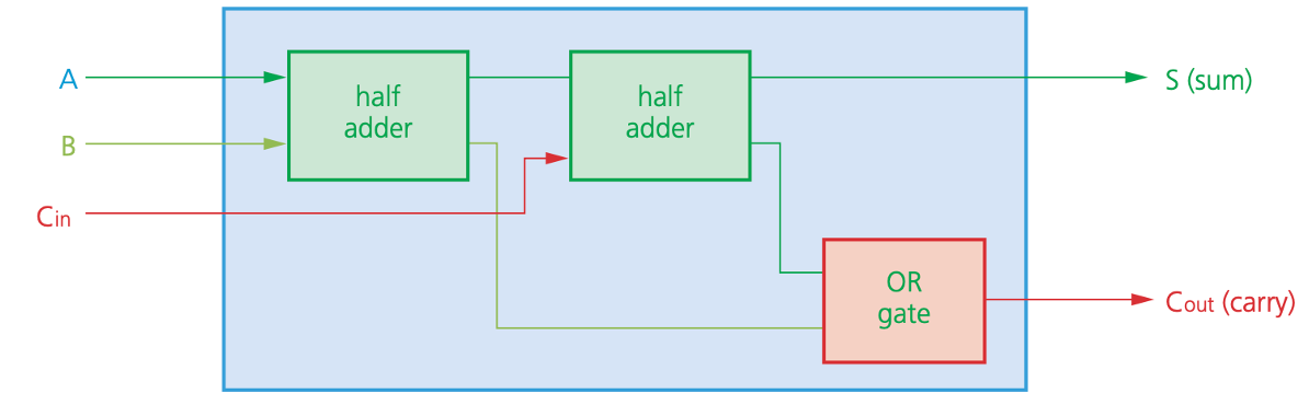
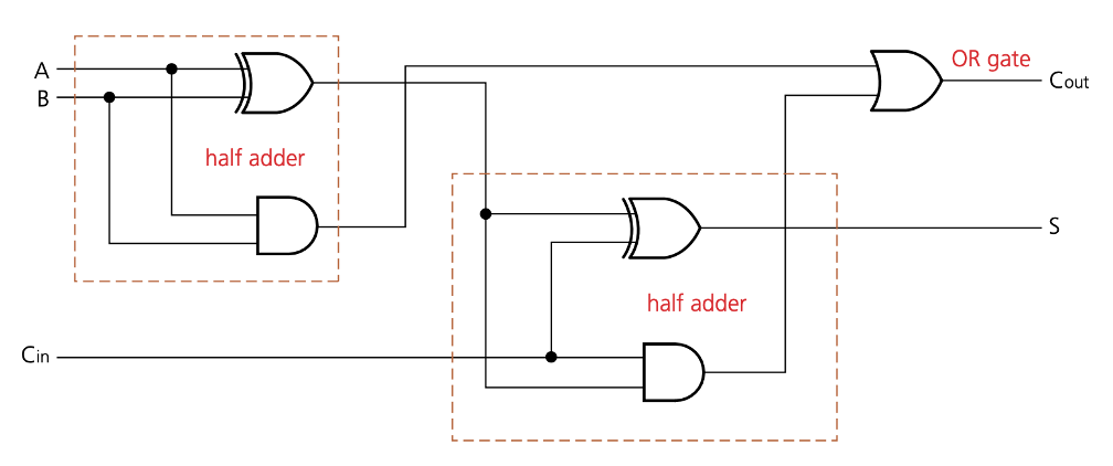
Full adder
The half adder is unable to deal with the addition of several binary bits (for example, an 8-bit byte).
To enable this, we have to consider the full adder circuit.
The sum shows how we have to deal with CARRY from the previous column.
There are three inputs to consider in this third column, for example, A = 1, B = 0 and C = 1 (S = 0).
| A | B | Cin | C | Cout |
|---|---|---|---|---|
| 0 | 0 | 0 | 0 | 0 |
| 0 | 0 | 1 | 1 | 0 |
| 0 | 1 | 0 | 1 | 0 |
| 0 | 1 | 1 | 0 | 1 |
| 1 | 0 | 0 | 1 | 0 |
| 1 | 0 | 1 | 0 | 1 |
| 1 | 1 | 0 | 0 | 1 |
| 1 | 1 | 1 | 1 | 1 |
Flip-flop circuits
All of the logic circuits you have encountered up to now are combination circuits (the output depends entirely on the input values).
We will now consider a second type of logic circuit, known as a sequential circuit (the output depends on the input value produced from a previous output value).
Examples of sequential circuits include flip-flop circuits. This chapter will consider two types of flip-flops: SR flip-flops and JK flip-flops.
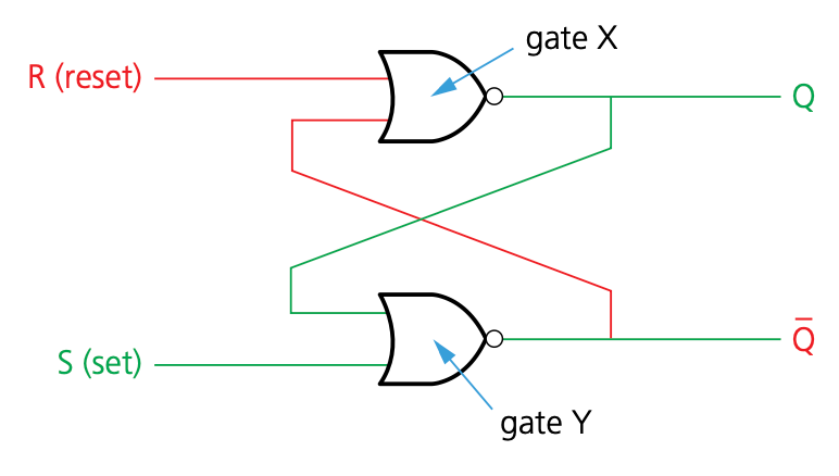
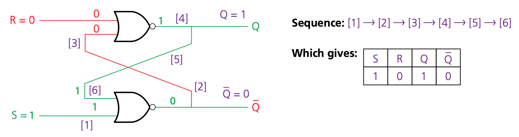
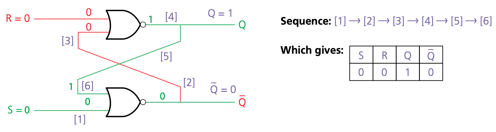
SR flip-flop
- SR flip-flops consist of two cross-coupled NAND gates, The two inputs are labelled ‘S’ and ‘R’, and the two outputs are labelled ‘Q’ and (‘𝑄’) ̅.
- The output from each NOR gate gives a form of positive feedback
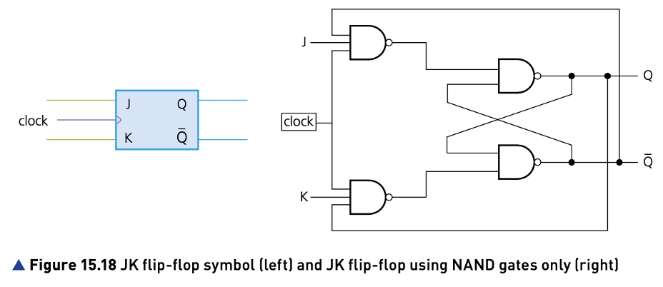
JK flip-flop
The SR flip-flop has the following problems:
- Invalid S, R conditions (leading to conflicting output values) need to be avoided.
- If inputs do not arrive at the same time, the flip-flop can become unstable.
To overcome such problems, the JK flip-flop has been developed.
A clock and additional gates are added, which help to synchronise the two inputs and also prevent the illegal states.
The addition of the synchronised input gives four possible input conditions to the JK flip-flop
- 1
- 0
- no change
- toggle (which takes care of the invalid S, R states).
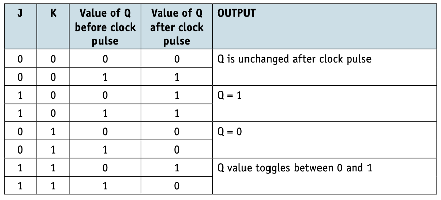
When J = 0 and K = 0, there is no change to the output value of Q.
If the values of J or K change, then the value of Q will be the same as the value of J (Q will be the value of K).
When J = 1 and K = 1, the Q-value toggles after each clock pulse, thus preventing illegal states from occurring (in this case, toggle means the flip- flop will change from the ‘Set’ state to the ‘Reset’ state or the other way round).
Boolean algebra and logic circuits
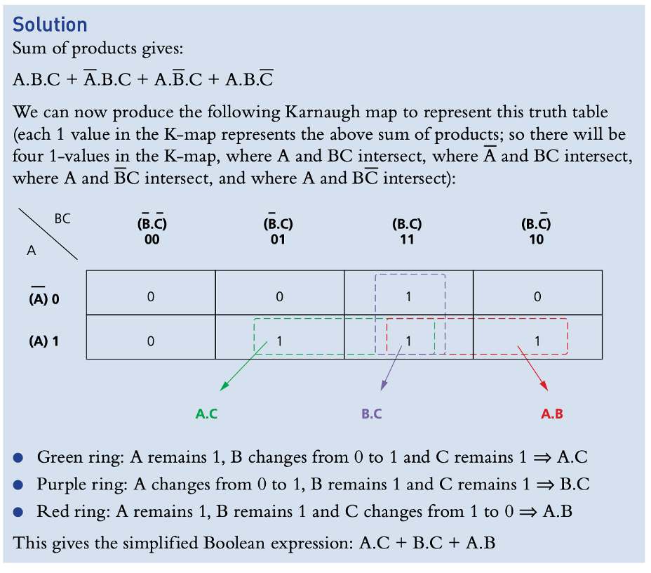
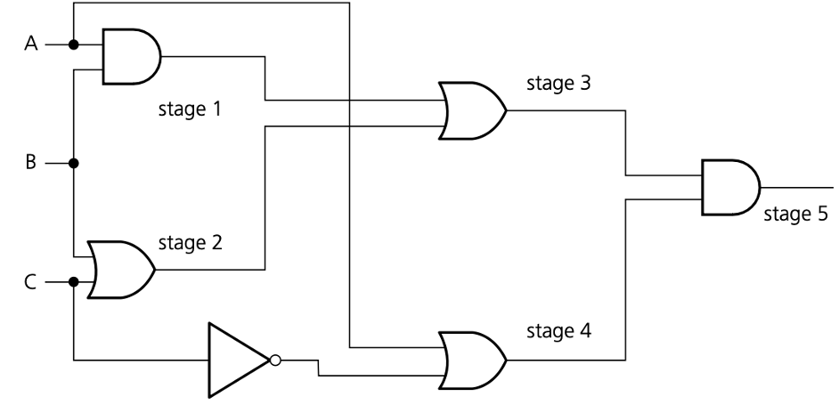
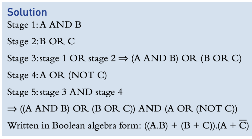
- It is possible to use the truth table and apply the sum of products (SoP), or the Boolean expression can be formed directly from the logic circuit.
Write down the Boolean expression to represent this logic circuit.
Karnaugh maps (K-maps)
- In the previous activities, it was frequently necessary to simplify Boolean expressions.
- Sometimes, this can be a long and complex process.
- Karnaugh maps were developed to help simplify logic expressions/circuits.
Karnaugh map rules
The values along the top and the bottom follow Gray code rules.
Only cells containing a 1 are taken account of.
Groups can be a row, a column or a rectangle.
Groups must contain an even number of 1s (2, 4, 6, and so on).
Groups should be as large as possible.
Groups may overlap within the above rules.
Single values can be regarded as a group even if they cannot be combined with other values to form a larger group.
The final Boolean expression can only consider those values which remain constant within the group (that is, remain a 1 or a 0 throughout the group).
- Produce a Boolean expression for the truth table for the NAND gate.
| Input | Input | Output |
|---|---|---|
| A | B | X |
| 0 | 0 | 1 |
| 0 | 1 | 1 |
| 1 | 0 | 1 |
| 1 | 1 | 0 |
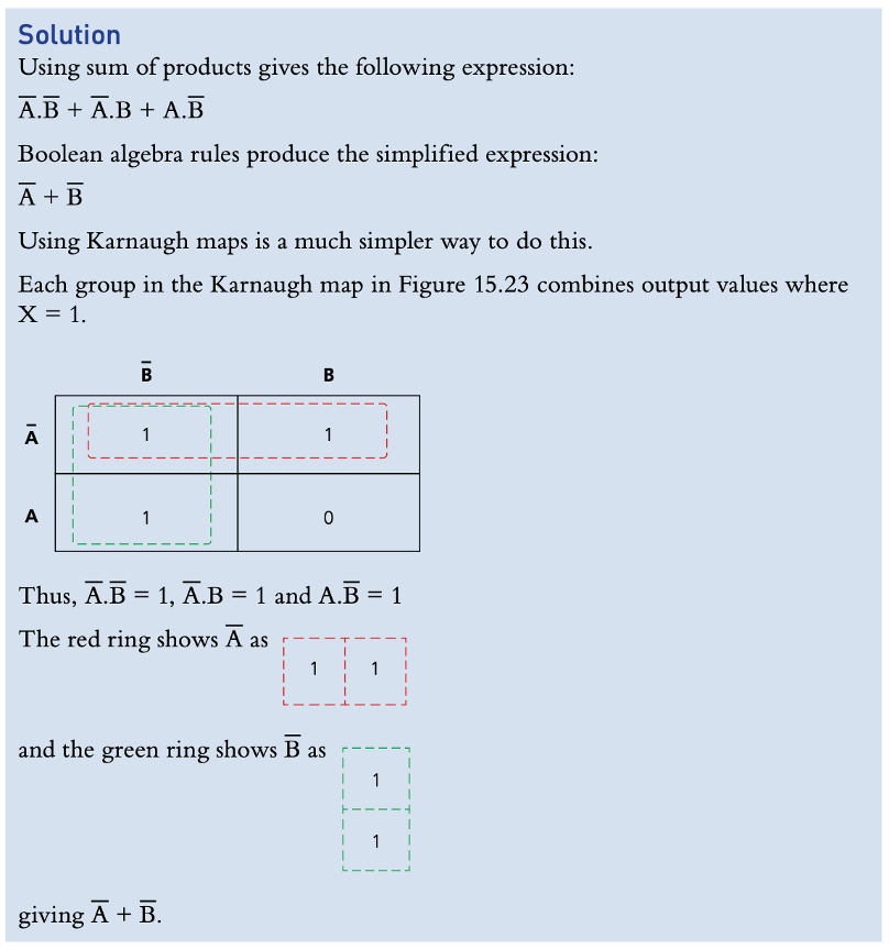
- Produce a Boolean expression for the truth table.
| A | B | C | X |
|---|---|---|---|
| 0 | 0 | 0 | 0 |
| 0 | 0 | 1 | 0 |
| 0 | 1 | 0 | 0 |
| 0 | 1 | 1 | 1 |
| 1 | 0 | 0 | 0 |
| 1 | 0 | 1 | 1 |
| 1 | 1 | 0 | 1 |
| 1 | 1 | 1 | 1 |